![[front of amp]](Images/JamesVRay/full-front.gif) |
![[controls]](Images/JamesVRay/top-front.gif) |
![[back of amp]](Images/JamesVRay/full-back.gif) |
![[speaker and serial number]](Images/JamesVRay/speaker.gif) |
| A late 60s Kalamazoo fashion statement. The
Tolex isn't really blue; that's an artifact of the flash.
This amp is very good condition. Corner scuffing is
evident. The grill cloth is darker than on earlier models.
CMI left the handle, jacks and fuse holder alone. |
The controls haven't really changed, but the
faceplate and knobs have. Control layout and spacing
are identical to older models. Internally, CMI
switched to only using two chassis bolts from four,
good enough but not as good. On the other hand,
the new cab design protects the controls somewhat. |
The back is similar to the older version,
except that five screws now hold each panel instead of four.
Other than minor rust on the screws and mild scuffing,
it still looks good. Note the poor bottom panel fit,
though. |
Every open-backed Kalamazoo (all but the bass
amps) has the serial number sticker on the speaker.
The speaker, transformers and wiring are all holding up
well. This amp has been kept somewhere with reasonably
controlled temperature and (relatively low) humidity
or there would be more rust evident. |
![[faceplate]](Images/BrianD/faceplate.gif) |
![[A Tale of 2 OTs]](Images/BrianD/two-ots.gif) |
![[OT wiring]](Images/BrianD/ot-wiring.gif) |
| Close up after surgery. This is
from a completely rebuilt Model Two, but who can tell?
The only obvious change to the front is the power switch
where the fuse used to be (it's now in the back,
underneath the chassis). The tone control switch no
longer does anything, though it could be wired up to
disconnect the tone control. The chassis is laying on
a clone Model Two cab I got off ebay. An amp's cabinet
is often one of the best places to put the chassis
while working on it. Since the customer only sent the
chassis, I used this one with the funky cover material.
What would you call this? Mauve snakeskin? |
The larger output transformer (OT)
is the new one. The smaller one has been set beside it
for comparison. The customer provided a Hammond 125DSE,
an 8 watt transformer with 5 output taps, suitable for
use for 2.5K, 5K or 10K nominal primary impedance. The
Kalamazoo Model One and Model Two need to see a primary
load in the vicinity of 4K to 5K. This allows possible
secondaries of 16, 8, 4, 2, or 1 ohm[s] (although
Hammond does not list 1 ohm, and it may be too much
current for the tranny; I haven't tested that). As
you can see, the Hammond is over twice the size of
the original. A bigger OT really opens these amps up.
|
The customer wanted the OT leads
intact in case he decided to reuse the Hammond at a
later date, or just to have other impedances available.
I ran the leads across the chassis, tied them with a
cable tie (and stick-on tie point), ran them back
across, shrink-wrapped the loose ends, and cable tied
the loose ends down. I added a hole with a grommet to
run the secondary leads back inside the amp next to the
new, shorting jack for the speaker (between the black/yellow
wires and the OT). I also installed a grommet where the
primary leads (blue/brown) enter the chassis. You can see
the fuse holder at the lower right, near the power cord.
|
![[the snake pit!]](Images/BrianD/snake-pit.gif) |
![[a gut transplant]](Images/BrianD/new-guts.gif) |
![[the main guts]](Images/BrianD/main-guts.gif) |
| Yes, from here it looks like a bit
of a snake pit. Actually, the power section looks like
one from most angles. I left the power transformer (PT)
wiring more or less in place, though I did add a cable
tie to keep it up in the air. I also ran the heater
wiring up in the air. There are a couple of ways to
run the wires to get the least noise; I prefer to keep
signal, ground and B+ wires next to the chassis (it's
a big ground plane), and run all AC wires in the air.
B+ is a crapshoot; I ran the 6BQ5 screen grid wire in
the air, too. After these photos were taken,
I put cable ties on the power cord on either side of the
grommet, and on the B+/ground wire bundle. The power supply
caps are all Sprague Atoms[tm].
|
It's not pretty. It's certainly not
a Hi-Watt. But it's rock solid, it has every bit of tone
you can get out of a Model Two, and it's very, very quiet.
About the only way to make it quieter is bigger filter
caps. It won't win any beauty contests for looks, but
I'll put the sound up against anything in its class.
The black cap and resistor across the yellow and blue
Atoms is the low voltage section of the heater bias
circuit. The black cap is a
100uF/100V Atom. The heater bias is tapped off the
screen supply, so it also adds more capacitance to
the screen, which means less hum there. Two quieteners
in one! I added more terminal strips, and replaced
one with a larger strip. While this adds to the visual
clutter, it allows me to take stress off the socket
terminal lugs. That's a good thing, because they tend
to break easily. At least half the Kalamazoos I see
have a broken socket lug, or one so weak that it breaks
from a light touch on a wire or component lead. That
long, yellow wire running across the middle is the
tremolo drive lead.
|
The customer sent all new resistors
and caps to match the bill or materials on my web page.
The green resistors are Kiwame carbon film resistors.
Most of the signal and trem caps are Orange Drop[tm] 715Ps.
The yellow cap on the tremolo terminal strip is a RelCap.
The cathode bypass cap at lower left is an REC. The
non-green resistors are metal oxides I provided for
things that weren't on the original BOM. None of these
are in the signal path, or even close. For instance,
the two large, gray resistors at the lower left are part of
the DC bias on the heater wires for hum reduction. I added
shielded wire where possible for signal runs. The amp
now has a "constellation ground"- a layered, star ground
scheme. The only violation is that the original input
jacks were used, which doesn't really cause a problem
since they have a proper star ground connection.
The output jack is also grounded, but since there is no
negative feedback loop, this is also not a problem. I
have no idea what the penciled writing is about!
|
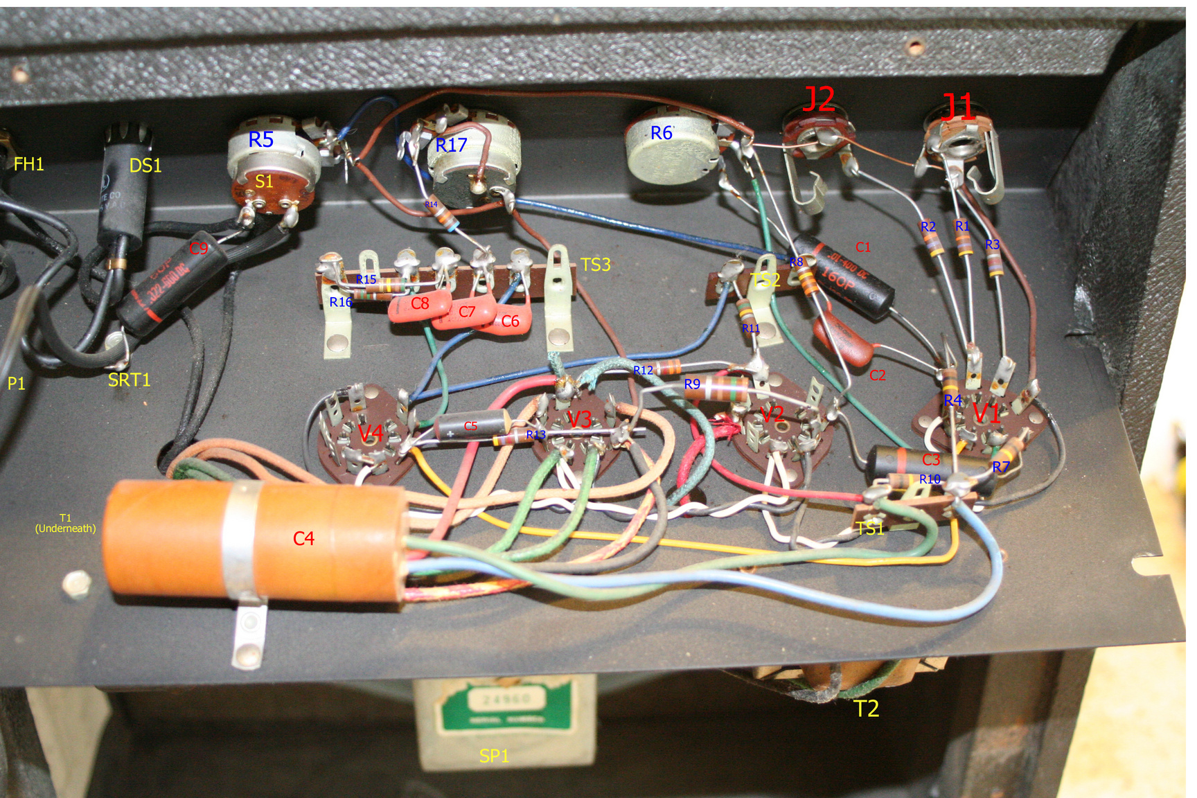
![[Annotated chassis!]](Images/AndyH/KalM2AnnChassis-tn.jpeg) Andy Hardy kindly sent this annotated photo of a nearly untouched Model Two chassis. All the
components are labeled except C10, the oscillation killer cap, which is either behind the terminal
strip TS1 (lower right) or simply missing on this amp.
Two versions available: 3456x2304, 2.3MB
and 1728x1152, 1MB.
Andy Hardy kindly sent this annotated photo of a nearly untouched Model Two chassis. All the
components are labeled except C10, the oscillation killer cap, which is either behind the terminal
strip TS1 (lower right) or simply missing on this amp.
Two versions available: 3456x2304, 2.3MB
and 1728x1152, 1MB. |
![[photo]](Images/photo-1.jpeg)
![[front of amp]](Images/JamesVRay/full-front.jpeg)
![[controls]](Images/JamesVRay/top-front.jpeg)
![[back of amp]](Images/JamesVRay/full-back.jpeg)
![[speaker and serial number]](Images/JamesVRay/speaker.jpeg)
![[faceplate]](Images/BrianD/faceplate.jpeg)
![[A Tale of 2 OTs]](Images/BrianD/two-ots.jpeg)
![[OT wiring]](Images/BrianD/ot-wiring.jpeg)
![[the snake pit!]](Images/BrianD/snake-pit.jpeg)
![[a gut transplant]](Images/BrianD/new-guts.jpeg)
![[the main guts]](Images/BrianD/main-guts.jpeg)